

Doppler Radar Receiver |
Description
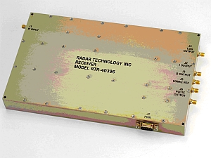
The RTR series of Doppler Radar Receiver was developed by RTI to measure the Doppler phase shift (I/Q Outputs) and intensity (Log output) in Radar applications.
Design Note: Radar Technology can customize any of our products to meet your individual system requirements. RTI also offers many Form, Fit, Function replacements to old RHG Electronics Amplifiers.
Features
- 10-350MHz Frequency Range
| IF Input | |
|---|---|
| Frequency | 30 or 60 MHz |
| Input Signal Level | -110 to -30 dBm |
| Input VSWR | < 2:1 |
| Bandwidths (other bandwidths up to 3MHz available at time of order) |
0.15 / 0.38 / 1.2 MHz (user selectable) |
| Logarithmic Amplifier output | |
| Load Resistance | 50 W |
| Slope | 25±1 mV/dB |
| Output Voltage: (user defined at time of order) |
1V±0.1V( IF input = -30 dBm) -1V±0.1V( IF input = -110 dBm; Bandwidth = 0.15 MHz) |
| Rise Time: | < 6mS (Bandwidth = 0.15 MHz) < 3mS (Bandwidth = 0.38 MHz) < 700 nS (Bandwidth = 1.2 MHz) |
| Fall Time: | <16 mS (Bandwidth = 0.15 MHz) < 8mS (Bandwidth = 0.38 MHz) < 2 mS (Bandwidth = 1.2 MHz) |
| I/Q output | |
| Load Resistance | 50 W |
| Maximum Voltage Swing (user defined at time of order) |
+-1 V |
| Amplitude Balance | ± 0.5 dB max |
| Phase Balance | ± 5 ° max |
| Pulse output | |
| Frequency | 30 or 60 MHz |
| Load Resistance | 50 W |
| Output VSWR | < 2:1 |
| Output level ( "on" state) | 5 ±1 dBm |
| Output level ( "off" state) | < -95 dBm |
| Video (TTL) leakage | 30 mV pp typ. |
| Rise/Fall Time | < 20 nS |
| Switching Time ( turn on/off) | < 30 nS |
| Reference output | |
| Frequency | 30 or 60 MHz |
| Load Resistance | 50 W |
| Output VSWR | < 2 |
| Output level | 5 ±1 dBm |
| Frequency Stability ( over temperature range –30 to +71°C) |
±2.5 ppm max |
| Phase Noise (20 KHz offset) | < -130 dBc/Hz |
| Power Supply current | |
| +15 V | <250 mA |
| -15 V | <400 mA |